W03 Learning Activity: Software Design
Overview
Software design, or planning, is the process of determining how software should be built. Design is the bridge that connects the business minded people (SDLC requirements phase) and the developers (SDLC implementation phase). It helps uncover and manage risks that may emerge in development. At its core, design is a communication tool to share ideas with others, and there is a careful balance between being thorough and being concise.
Failure to properly design software can result in costly errors later in the software development lifecycle (SDLC).
Key Points to Remember:
- Taking time to design software can identify and mitigate risks early in the SDLC.
- There are many ways to document design, from very formal to very informal. Choose the approach that matches your team and its goals.
Preparation Material
Once you have determined the requirements of the system, product, or feature that should be built, the next step is to design the solution. Designs can be formal or informal. They can be done at a system level, or at a detailed component level. The important thing is that by planning out a solution, you can communicate ideas with others and uncover risks.
Connection to Requirements
Software design is directly connected to the requirements elicitation phase that precedes it. During the design phase you translate the requirements you have gathered into a structured plan or blueprint that shows how the system will fulfill those needs.
In addition, during the design process, any ambiguities or inconsistences in the requirements are often identified. This can lead to an iterative feedback loop where the designers go back to the stakeholders for clarification to improve and update the documented requirements.
Traceability
Traceability is the idea that every part of the design should be able to be traced back to something in the requirements documentation. Traceability ensures that each component, module, or feature in the design ties back to a requirement, and that no requirements are overlooked.
As you will see in future learning activities, traceability also extends to future phases of the SDLC as well, where other artifacts such as test cases directly trace back to requirements. Similarly, each part of the implementation should be able to be traced back to a design element, which can then be traced back to one or more requirements.
Effective designs serve as a guide for developers during the implementation phase, ensuring that the system is built according to the specified requirements and design constraints.
Design as a Communication Tool
One of the important aspects of software design is that it serves as a communication tool. It helps facilitate communication of ideas within the development team, between the development team and business stakeholders, and between current developers and those who will maintain the software in the future.
Communication with Business Stakeholders
Software design can facilitate communication with business stakeholders in several ways including:
- Visual Clarity: Design tools such as wireframes, mockups, and UML diagrams provide a visual representation of the system. These visuals make it easier for business stakeholders to understand the system's functionality and structure without needing deep technical knowledge.
- Requirement Verification: Design documents can be used to verify that the requirements elicited from business stakeholders are correctly understood and accurately reflected. This ensures that the final product will meet their expectations and business needs.
- Early Feedback: By presenting design artifacts early in the development process, stakeholders can provide feedback on the proposed solution. This iterative process helps catch potential issues early and align the design with business goals.
- Clarifying Scope and Features: Design documents help clarify the scope of the project and the features to be implemented. This ensures that all stakeholders have a clear understanding of what will be delivered, reducing the likelihood of scope creep and misunderstandings.
- Risk Communication: Design documents can highlight potential technical risks and challenges. By discussing these risks with business stakeholders, the team can develop mitigation strategies and set realistic expectations regarding timelines and deliverables.
- Documentation and Reference: Detailed design documents provide a reference that business stakeholders can revisit at any time. This ensures that everyone has access to the same information and can help resolve any disputes or misunderstandings that arise during development.
- Facilitating Decision-Making: Clear design documents provide the information needed for stakeholders to make informed decisions about project priorities, resource allocation, and potential trade-offs.
Communication among Developers
Software design also helps facilitate communication among developers in several ways, including:
- Unified Understanding: A well-documented design ensures that all developers have a shared understanding of the system's architecture, components, and interactions. This common framework reduces misunderstandings and aligns the team's efforts.
- Clear Specifications: Design documents provide clear specifications for each component, module, and interface. Developers can refer to these documents to understand the exact requirements and constraints, minimizing ambiguity.
- Standardized Terminology: Design documents establish standardized terminology and conventions, ensuring that all developers use the same language when discussing the system. This consistency aids in clear and effective communication.
- Code Consistency: Design guidelines and patterns promote consistency in coding practices across the team. Consistent code is easier to read, understand, and maintain, which improves collaboration and reduces errors.
- Documentation and Diagrams: Visual tools such as UML diagrams, flowcharts, and sequence diagrams provide intuitive representations of the system's structure and behavior. These tools make complex interactions easier to grasp and discuss.
- Reference Material: Detailed design documents serve as a reference for developers throughout the project. When questions or uncertainties arise, developers can consult the design documents to find answers and ensure they are adhering to the agreed-upon plan.
- Facilitating Code Reviews: Design documents provide a basis for code reviews and discussions. Reviewers can compare the implemented code against the design to ensure it meets the specified requirements and adheres to the design principles.
- Change Management: When changes are proposed, design documents help assess their impact on the system. Developers can discuss and evaluate changes in the context of the overall design, ensuring that modifications are made thoughtfully and systematically.
- Mentoring and Onboarding: For new team members, design documents provide an essential overview of the system. They help new developers quickly understand the architecture and design principles, facilitating smoother onboarding and integration into the team.
- Cross-Team Collaboration: In larger projects, different teams might work on different parts of the system. Design documents help coordinate efforts across teams, ensuring that interfaces and dependencies are clearly defined and understood by all parties involved.
Communication for Future Use
Software design also plays a critical role in communicating knowledge and understanding to future developers.
As software evolves over time and bugs need to be fixed or new features need to be added, it is important for the developers to be able to refer back to design documentation (and the requirements they trace back to) to understand the reasons behind previous decisions and the interfaces between various system components.
Finally, there are often decisions, practices, processes, and insights that are known informally within a team or organization but are not documented or officially recorded. Sometimes this type of knowledge is referred to as "tribal knowledge". It is typically passed down through direct communication and experience, rather than through formal documentation or training. This type of knowledge can be very important, but is often lost because of the lack of documentation. Clear, documented software design artifacts preserve this knowledge more effectively for future developers.
Mitigating Risks
A common theme throughout all the phases of the SDLC is to identify and mitigate risks as early as possible. Effective software design can help mitigate risks later in the project by providing a structured and thoughtful approach to planning and building the system. The following are some of the ways that design can mitigate risks:
- Requirement Misinterpretation: By translating requirements into detailed design specifications, software design ensures that all stakeholders have a clear and shared understanding of what the system should do. This reduces the risk of building something that does not meet the users' needs or expectations.
- Complexity Management: Design helps break down a complex system into smaller, manageable components. This modular approach makes it easier to understand, develop, test, and maintain each part of the system, reducing the risk of errors and integration issues.
- Early Problem Detection: During the design phase, potential technical challenges and issues can be identified and addressed before they become significant problems. This proactive approach helps mitigate the risk of costly and time-consuming rework later in the development process.
- Consistency and Standardization: Design documents establish coding standards, design patterns, and best practices, promoting consistency across the development team. This reduces the risk of bugs and vulnerabilities caused by inconsistent or poor coding practices.
- Scalability and Performance: Thoughtful design considers scalability and performance requirements, ensuring that the system can handle increased load and perform efficiently. This reduces the risk of performance bottlenecks and system failures under high demand.
- Security: Incorporating security considerations into the design phase helps identify potential vulnerabilities and threats early on. Designing with security in mind reduces the risk of security breaches and data leaks.
- Change Management: A well-documented design provides a clear blueprint for the system, making it easier to understand the impact of proposed changes. This helps manage the risk of unintended consequences when modifications are made to the system.
- Maintainability and Extensibility: Designing for maintainability and extensibility ensures that the system can be easily updated and extended in the future. This reduces the risk of technical debt and makes it easier to incorporate new features and fix issues.
- Documentation and Knowledge Transfer: Design documents provide a reference for current and future developers, ensuring that knowledge is preserved and transferred effectively. This mitigates the risk of knowledge loss when team members leave or new members join.
- Regulatory and Compliance: A well-thought-out design considers regulatory and compliance requirements, ensuring that the system meets legal and industry standards. This reduces the risk of non-compliance and associated penalties.
Many of these issues can be dealt with later in the project, but identifying and addressing these risks during a planning phase helps reduce costs and avoid unforeseen circumstances in major ways.
Design Patterns and Best Practices
During design, experienced software engineers draw on their knowledge of common design patterns and best practices.
A software design pattern is a general, reusable solution to a common problem that occurs in software design. It is a template or blueprint that can be applied to specific situations in the development of software. Design patterns are not finished designs that can be directly transformed into code, but rather templates or guidelines that help solve design problems in a particular context. Here are some key aspects of software design patterns:
- Reusability: Design patterns capture best practices and solutions that can be reused across different projects and scenarios, helping to avoid reinventing the wheel.
- Abstraction: Patterns provide an abstract solution that can be implemented in various programming languages and environments. They focus on solving the design problem rather than the specifics of the implementation.
- Common Language: Design patterns provide a common vocabulary for developers to discuss and share design solutions. Using pattern names (for example, Singleton, Observer, Factory) facilitates clear and concise communication among team members.
There are whole courses, books, and websites devoted to design patterns. While this course does not cover them deeply, it would be valuable to learn more about them in another setting.
Levels of Design
Software design involves planning and specifying different aspects of a software system at various levels of detail. The following is a breakdown of the levels of software design, starting from the larger architectural design down to the finer details within a function:
Architectural Design
Architectural design establishes the overall structure and organization of the software system. It defines how major components or modules interact with each other and how the system as a whole achieves its goals.
- Components: At this level, the major architectural components of the system are defined, such as modules, layers (for example, presentation layer, business logic layer, data access layer), and subsystems.
- Focus: The focus is on high-level decisions regarding system architecture, including design patterns, architectural styles (for example, client-server, microservices), and deployment strategies.
- Outputs: Architecture diagrams (for example, UML diagrams, component diagrams), system specifications, technology stack decisions, and high-level design documents.
Component Design
Component design elaborates on the architectural components identified in the previous step. It defines the internal structure and behavior of each component.
- Components: Each component identified in the architectural design is detailed further, specifying the classes, objects, methods, and their relationships within the component.
- Focus: This level focuses on how each component achieves its specific functionality, including detailed design patterns, algorithms, data structures, and interfaces between internal components.
- Outputs: Detailed component diagrams, class diagrams, sequence diagrams, and component specifications.
Module Design
Module design (sometimes considered part of component design) zooms in on individual modules or subsystems within the components identified earlier.
- Components: At this level, larger components are broken down into smaller, manageable modules or units of functionality. Each module may encapsulate related functions or services.
- Focus: Designing modules involves specifying the detailed interactions between classes and functions within the module, defining interfaces, and ensuring cohesion and low coupling.
- Outputs: Module interface specifications, module dependency diagrams, and detailed module documentation.
Class Design
When using object-oriented programming, class design focuses on the design of individual classes within the modules identified in the previous steps.
- Components: Each module contains multiple classes that represent entities, behaviors, or services within the module. Class design specifies the attributes, methods, and relationships of each class.
- Focus: The focus is on designing the internal structure of each class, including attributes, methods, inheritance hierarchies, and associations with other classes.
- Outputs: Class diagrams (for example, UML class diagrams), detailed class specifications, and method specifications.
Function or Method Design
Function or method design details the implementation of individual functions or methods within classes.
- Components: Functions or methods encapsulate specific behaviors or operations that manipulate data or perform computations.
- Focus: This level of design specifies the algorithmic details, input parameters, return values, error handling mechanisms, and local variables within each function or method.
- Outputs: Pseudo-code, flowcharts, detailed function specifications, and API documentation for public methods.
Example: Order Processing System
The following provides examples of each of these levels in the context of an order processing system.
- Architectural Design: Defines modules like Order Management, Inventory Management, and Customer Management, and how they interact using a microservices architecture.
- Component Design: Details the Order Management module, specifying classes like
Order,OrderService, andOrderRepository, along with their relationships and responsibilities. - Module Design: Breaks down the
OrderServicemodule into smaller units likecreateOrder,cancelOrder, andupdateOrderStatus, each handling specific operations. - Class Design: Designs the
Orderclass with attributes such asorderId,customerId, andorderItems, along with methods likecalculateTotalPrice()andaddItem(). - Function or Method Design: Specifies the
calculateTotalPrice()method within theOrderclass, detailing how it iterates throughorderItemsto calculate the total price and handle discounts.
Defining Interfaces
At any level of design, one of the most important pieces to plan out is the interface between two different components of a system. This interface becomes a type of contract that each component can rely on to establish shared expectations.
Diagrams and Design Tools
There are established tools and techniques for describing the various parts of design. The following are examples of some of the most common tools.
UML Class Diagrams
One of the most common design tools is the UML (Unified Modeling Language) class diagram, which represents classes, their attributes, operations or methods, and the relationships among classes. UML class diagrams are widely used in software engineering for visualizing, specifying, constructing, and documenting the architecture of software systems.
The following are the major components of UML class diagrams:
- Classes: Represented as rectangles with three compartments:
- Top compartment: Class name.
- Middle compartment: Attributes (data members or fields).
- Bottom compartment: Operations (methods or functions).
- Attributes: Properties or data members of a class that describe its state.
- Shown in the middle compartment of the class rectangle.
- Typically includes the name of the attribute and its data type.
- Operations: Methods or functions that define the behavior of a class.
- Shown in the bottom compartment of the class rectangle.
- Includes the operation name, parameters (if any), return type, and sometimes visibility (public, private, protected).
- Relationships: Connections or associations between classes, indicating how they interact or
collaborate. Common relationships include:
- Association: A structural relationship representing a connection between two or more classes, often with multiplicity (for example, one-to-one, one-to-many).
- Generalization (Inheritance): Shows inheritance relationships between classes, where one class (subclass or derived class) inherits attributes and operations from another (superclass or base class).
- Dependency: Indicates that one class depends on another in some way, often through method parameters or return types.
- Aggregation: Indicates a whole-part relationship, where one class is part of another class (for example, a car has parts like engine, wheels).
- Composition: Stronger form of aggregation where the lifetime of the part (component) is controlled by the whole (composite).
- Visibility: Specifies the access level or visibility of attributes and operations:
- Public (+): Accessible from outside the class.
- Private (-): Accessible only within the class.
- Protected (#): Accessible within the class and its subclasses (inheritance).
The following is an example of a UML class diagram.
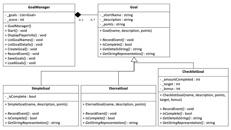
UML class diagrams are an effective way to communicate the expectations of classes in an object-oriented system.
UML Sequence Diagrams
Another very common design tool is the UML sequence diagram. Unlike class diagrams that highlight the static structure of a system, sequence diagrams show interactions among objects in a sequential manner over time. They illustrate how objects collaborate with each other to achieve a specific behavior or scenario within a system. Sequence diagrams are particularly useful for visualizing the flow of messages, method calls, and control flow between objects during the execution of a use case or a system operation.
The following are the key components of a UML sequence diagram:
- Actors and Objects:
- Actor: Represents an entity (user, system, external component) interacting with the system.
- Object: Represents an instance of a class or component within the system.
- Lifelines:
- A lifeline represents the existence of an object over a period of time during which it participates in interactions.
- Drawn as a vertical dashed line attached to the top of the object's symbol.
- Messages:
- Messages are depicted as arrows between lifelines, indicating communication or interaction between objects.
- Synchronous Message: Indicates a direct call where the sender waits for the receiver to complete the operation before proceeding.
- Asynchronous Message: Indicates a call where the sender continues without waiting for the receiver to complete the operation.
- Return Message: Indicates the response returned from a method call, showing the flow of control back to the sender.
- Activation Boxes:
- Activation boxes represent the time period during which an object is performing an operation or processing a message.
- Shown as a rectangle on top of the lifeline with vertical lines extending downwards.
- Control Flow:
- Control flow arrows show the sequence of messages and the order in which interactions occur between objects.
- They help illustrate the chronological order of method calls and responses during the execution of a scenario.
The following is an example of a UML sequence diagram.

Data Dictionaries
Another common tool used in design is a data dictionary, which is a centralized repository or document that provides detailed descriptions and definitions of data elements used within a system. It serves as a comprehensive reference for data management, helping to ensure consistency, accuracy, and clarity in data usage throughout the system.
The following are key components of a data dictionary:
- Name: The unique identifier or label used to reference the data element.
- Description: A detailed explanation of the data element, including its purpose, usage, and context within the system.
- Data Type: Specifies the type of data the element represents (for example, integer, string, date).
- Length: Defines the maximum length or size of the data element (applicable for string or numeric data).
- Format: Describes the format or structure of the data element, such as date formats or currency symbols.
- Valid Values: Lists acceptable values or ranges that the data element can hold.
- Constraints: Any additional rules or restrictions that apply to the data element (for example, mandatory, optional, unique).
The power of data dictionaries is that they clearly show the data that is going back and forth between components, including the data types and other details. This is especially important when defining APIs or any kind of interface.
Data dictionaries are ideally defined before a component is built, but they can also be generated directly from the code after the fact.
Amount of Detail
In addition to the few common design tools discussed here, there are many others. As you consider each of these tools and the designs for the various parts of your system, you will have to make a decision on how formal or informal you will be.
Much like the tradeoffs between formal and agile methodologies, there are advantages and disadvantages to being more formal, and also to being more thorough and detailed. You might be tempted to say that being more formal and detailed is always better, but remember that agile methodologies prefer working code to comprehensive documentation.
When designs are more formal and detailed, they can become more difficult to maintain, and often get out of sync with the current system. On the other hand formal designs can often be more precise and avoid the ambiguity that arises from lack of detail.
You should also recognize that you can use formal tools, but lack important detail, or you can be informal in the tools (such as using a whiteboard for a diagram) while at the same time being very thorough. Most companies will define a standard that you will follow with regard to the tools they use, but perhaps the most important aspect to consider when making a decision is that you want to choose a process that your team can reliably use and maintain. A design that is not used, or one that gets out of date and is not maintained is likely worse than not having one at all, because it could convey false information.
Design in an AI World
As artificial intelligence becomes more prominent in the software engineering field, the importance of creating high quality software designs becomes more important than ever. Code generation tools excel at writing code when the problem is very well defined. As time goes on, it may be that engineers spend nearly all of their time in the design, review, and testing phases, and very little in the actual implementation work.
Continue the conversation
After completing this reading, ask 3-5 follow up questions about software design to an AI system of your choice. (You may use ChatGPT, Bing, Claude AI, Gemini, or any other system of your choosing.)
Good questions may include:
- Explain _______ (such as UML, sequence diagrams, design patterns, architectural design)
- What is an example of a sequence diagram?
- What are the benefits of design patterns?
- Why do software developers skip design?
- How much design is required in a software project?
Submission
After you are comfortable with these topics, return to Canvas to take the associated quiz.
Other Links:
- Return to: Week Overview | Course Home
ChatGPT assisted in the creation of this learning material.